Increasingly engineers, landscape architects, and design professionals are seeking ways to comply with Phase II of the National Pollution Discharge Elimination Program (NPDEP), various local, state, and federal requirements of the Water Pollution Control Act, and many state laws and regulations promulgated to control of water pollution and storm water pollution.
The state of Maryland has been a leader in stormwater management designs, and BMP's from the state and from Maryland counties like Montgomery have set the norms for many states.
What follows is a design for biofiltration that was developed and promulgated by the Department of Permitting Services, Water Resources Section, County of Mongomery.
BIOFILTRATION (BF)
The biofiltration methods described in the following section are based on the bioretention design found in the Maryland Stormwater Design Manuel, and where deemed appropriate, have been modified by the Montgomery County Department of Permitting Services. DPS currently restricts the use of biofiltration (BF) for the treatment of the water quality volume from catchment areas of 1.0 acre or less. In addition, unless waived by DPS all biofiltration devices shall include a PVC pipe underdrain system.
A. Facility Description
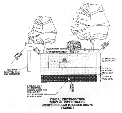
Biofiltration is a soil filtration system. Principal components of the system (figures 1&2) include:
- a pretreatment grass filter strip,
- surface planting with woody and herbaceous plant species,
- a surface 2-3 inch thick mulch layer,
- a minimum 2 foot thick sandy loam or loamy sand soil-textured planting soil media (See specifications),
- a 6-inch thick sand layer, and f.) perforated PVC pipe underdrainage within a 15-inch thick gravel bed.
The entire system can generally fit into a relatively confined space, thus making it well suited for incorporation within parking lot designs.
It is strongly recommended that stormwater runoff sheet flow through a grass filter strip into the ponding area. A maximum 12-inch deep ponding depth has been selected so as to reduce the likelihood of creating saturated-soil/anoxic conditions within the system. The perforated PVC pipe underdrain system provides proper drainage and aeration of the planting soil filter layer. Volumes above the water quality volume will pass through the facility via a structural overflow. Excess runoff that cannot be filtered is diverted away from the biofiltration area via a graded grassed swale or similarly acceptable drainage technique.
|
- Applicability
The biofiltration device is appropriate for drainage areas of I acre or less, such as parking lots and building additions in highly visible areas. Large biofiltration structures can be expensive to properly landscape and maintain.
- Design Storm
The facility must be sized to provide storage for the required water quality volume, Peak flows from the 10-year frequency storm must be safely conveyed around the basin whenever possible. See Montgomery County Flow Splitting Criteria.
- Groundwater
In general, the BF system cannot be located where the water table is within 6 feet of the ground surface. In situations where groundwater is encountered, another method for water quality treatment should be considered.
-
Embankment Criteria
As shown in (figure 1) the BE utilizes an embankment with a minimum top width of four feet, maximum 3:1 side slopes and a core trench. It is imperative that the appropriate underdrain excavation, core trench, and all backfill and embankment requirements are met, since these are permanent facilities. Refer to "Construction Specifications for Shallow Facilities",
- Sizing
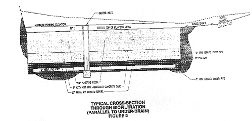
The facility must be sized to store the required water quality volume (WQV). As previously indicated, the maximum ponding depth above the filter bed area is 12-inches. The facility shall be constructed to a 9-inch depth to allow for settlement. Storage is computed above the surface of the facility. The top of the filter media must be level across its entire surface.
Storage volume is determined from the top of the planting media to the crest of the outlet weir or invert of the flow splitter overflow pipe, whichever is lower.
Note: Biofiltration devices should not be located in areas where the water table is within six feet of the ground surface, within areas which contain mature trees or other environmentally sensitive site features, or where existing slopes exceed 15 percent.
To the extent possible, structures should have irregular outlines to blend naturally into the environment. Rectangular is not natural
- Stormwater Discharge Into Biofiltration Area
Pretreatment through a grass filter is preferred whenever possible. Pretreating runoff may extend the life of the facility. A typical location for the pre-treatment grass filter strip or swale is along the back portion of the facility, adjacent to the planting media. Maximum velocities into the grass filter may not exceed three (3) fps. Particular care must also be taken to prevent erosion of the surface mulch layer. DPS recommends that maximum design storm velocities across the filter bed area not exceed one (1) fps.
- Overflow Weir Sizing Criteria
Design of the overflow weir, if required, is largely dependent upon the way flows are delivered to the facility. Refer to "Montgomery County Flow Splitting Criteria". Generally, the overflow weir design is as follows:
- An overflow weir may not be required where a minimum of one foot of freeboard is provided above the 10-year water surface elevation in the facility.
- If an overflow weir is necessary, it can be similar to a small emergency spillway and must be located at existing ground level or in cut. If the facility is not fed by a flow-splitter, size the weir to safely pass the full 10-year storm.
If the facility is fed by a flow-splitter, outlet weir sizes may be reduced, with the outlet weir sized to safely pass whatever portion of the 10-year storm is delivered to the facility. In this case, protection may be provided by permanent turf reinforcement matting only. Utilization of turf reinforcement matting should be considered wherever stream thermal concerns are an issue.
Individualized designs to safely pass either a flow-split 0 or the 10-year storm, both with one foot of freeboard, are necessary. Provide a safe non-erosive outlet below the outfall.
- An overflow weir may not be required where a minimum of one foot of freeboard is provided above the 10-year water surface elevation in the facility.
- Underdrain Pipe
The underdrain pipe consists of 6-inch diameter schedule 40 or stronger perforated PVC pipe at 0.00% slope. The underdrain pipe will be placed within the gravel layer. Three inches of gravel must be placed under the pipe, with a minimum of 6 inches of gravel over the pipe. Perforations must be 3/8 inch in diameter and must be located 4 inches on center, every 90 degrees around the pipe. Perforated pipe must begin at least 5ft inside the filter media. Filter fabric must not be wrapped around the underdrain pipe.
Access for cleaning all underdrain piping is needed. Clean-outs for each pipe should extend 6 inches above the top of the planting media and have a removable waterproof cap.
The required number of underdrain pipes is proportional to the surface area of the biofiltration device. To determine the number of underdrain pipes, multiply the surface area square footage by 0.05. This determines the linear feet of piping required. Use a minimum of two pipes whenever possible. For example, if the surface area of the biofiltration device is 450 square feet, then:
450 (0.05)= 22.5 LF (This should be rounded to the nearest foot,)
Thus, the requirement will be for two underdrain pipes, each 11 feet long. Underdrain pipes should be placed a minimum of 5' apart.
- Gravel Bed
The gravel layer surrounding the underdrain pipe(s) must meet MSHA size #7 (Table 901A), and must provide a minimum of 6 inches cover over the pipe(s), and minimum 3 inches under the pipe. No geotextile or filter fabric is allowed anywhere within the filter media (stone and sand).
- Sand Bed
A minimum 6-inch fine aggregate sand layer shall be provided below the soil filter/planting media. A sand window shall extend from the sand filter to the surface of the planting media opposite from the inflow point. (figure 1). The sand window will be a minimum of 10 sq. ft. ASTM C33 Fine Aggregate Concrete Sand is required. Manufactured sand or stone dust is not acceptable.
- Drawdown Time
Drawdown time must be designed to be between 12-24 hours. This will allow the facility to be free to treat consecutive storms, while increasing the treatment time to provide for adequate pollutant removal. Drawdown computations must be submitted to DPS for review. A removable, watertight perforated underdrain cap (1 inch minimum opening) may be used to achieve the drawdown requirement. The perforation must be at the invert elevation of the underdrain pipe. In thermally sensitive watersheds, a 12-hour drawdown time must be used.
- Soil Filter/Planting Media
The planting media shall consist of 1/3 perlite, 1/3 compost and 1/3 topsoil . The perlite shall be coarse grade horticultural perlite. The compost shall be high-grade compost free of stones and partially composted woody material. The soil shall meet the following minimum criteria: contain no more than 10% clay, 30 - 55% silt and 35 - 60% sand. The soil shall be free of stones, stumps, roots or other similar objects larger than 2 inches. 'The first layer of the planting media shall be lightly tilled to mix it into the sand layer, so not to create a definitive boundary. The planting material shall be flooded after placement . Any settlement that occurs shall be filled back to the design elevation.
- Mulch
The mulch layer is an important part of the BF. Much of the pollutant removal capacity of the BF is within the mulch layer. The surface mulch layer will consist of standard fine shredded aged hardwood mulch. The mulch should be applied uniformly to a depth of 2 to 3 inches. Yearly replenishing may be necessary. Pine bark is not acceptable.
- Plant Materials
Plants, through their pollutant uptake and evapotranspiration of stormwater runoff, play a key role in the overall effectiveness of the biofiltration device. Both the number and type of tree and shrub plantings for the system may vary, especially where aesthetics or other considerations are critical to site development. While native plants are encouraged, they are not always appropriate in all situations. While no hard planting rule exists, the plants should be a mix of trees, shrubs and herbaceous materials. However, there should be 2 to 3 shrubs planted per tree and herbaceous plantings shall make up 40 % of the total number of plants. Trees shall be a minimum of 2 % in. caliper, shrubs shall be minimum 2 gal. size and herbaceous plants shall be a minimum 1 gal size. Mature plant canopy should cover 85 % of the BF. A landscape plan will be required as part of the plan. The plan will be sealed by a registered landscape architect. Since the plants are an integral part of the BE, no changes to the approved landscape plan will be allowed without prior approval from DPS. An 85% survival rate after 18 months will be required before the as built plan is approved.
Appendix A contains a list of unacceptable plants.
Acer platanoides
Acer pseudoplatamus
Ailanthus altissima
Ampelopsis brevipedunculata
Berberis thunberaii
Carduus acanthoides
Carduus nutans
Catalpa sp.
Celastrus or biculatus
Centuria maculosa
Coronilla varia
Eleagnus angustifolium
Eleagnus umbellata
Eulalia vimineus
Euonymus alatus
Euonymus fort unel
*Hedera helix
* Hemerocallisfulva
Ligusrrum sp.
Lonicera sp.
Lonicerajaponica
Lysimacizia nummularia
Lythrum alatum
Morwc alba
Myoston aquaticwn
Faulownia tamenrosa
Phellodendron amurense
Picea glauca
Prunus avium
Rhamnu.s' cathartica
Rhamnusfrangula
Rubus illecebrosus
Rubusphoenicolasfus
Spiraeajaponica
Symphoricarpos orbiculatizc
*Vinca minor
Wisteria floribunda
Wisteria sinensis
Norway Maple
Sycamore Maple
Tree of Heaven
Porcelain Berry
Japanese Barberry
Plumeless Thistle
Musk Thistle
Catalpa
Oriental Bittersweet
Spotted Knapweed
Crown Vetch
Russian Olive
AutumnOlive
Beefsteak Mint
Winged Euonymus
Climbing Euonymus
English Ivy
Common Daylily
Privet
Bush Honeysuckles
Japanese Honeysuckle
Moneywort
Purple Loosestrife
White Mulberry
Moncywort
Empress Tree
Arnur Cork Tree
White Spruce
Sweet Cherry
Common Buckthorn
European Buckthorn
Strawberry Raspberry
Wineberry
Japanese Spirea
Coralberry
Periwinkle
Wisteria
Chinese Wisteria
Tree
Tree
Tree
Vine
Shrub
Herbaceous
Herbaceous
Tree
Vine
Herbaceous
Herbaceous
Shrub
Shrub
Herbaceous
Shrub
Vine
Vine
Herbaceous
Shrub
Shrub
Vine
Herbaceous
Herbaceous
Tree
Herbaceous
Tree
Tree
Tree
Tree
Shrub
Shrub
Shrub
Shrub
Shrub
Shrub
Vine
Vine
Vine
- Mulch
A Typical BIOFILTRATION Design
|
|
|
For more information about stormwater management designs, go to
- Stormwater Management with Perlite and Vermiculite.
- The Stormwater Manger's Resource Center ---The Stormwater Manager's Resource Center (SMRC) web site is made possible through a grant from the Environmental Protection Agency, Office of Water, Office of Wastewater Management, Assistance Agreement #828077-01. The SMRC site is managed and published by the Center for Watershed Protection, Inc., a 501(c)3 organization located in Ellicott City, Maryland.
For more information about these uses of perlite in gardening, Greenroofs, turf grass applications, landscaping, and container growing see our main horticultural page , please call or contact us at:
The Schundler Company
10 Central Street
Nahant, MA 01908
(ph)732-287-2244
www.schundler.com
email: info@schundler.com
Back to Horticultural Main Page